

It can be shown mathematically that any source of power e.g. a receiver antenna, an audio amplifier or an amateur radio transmitter will deliver its maximum possible power output when the impedance of the subsequent load is equal to the internal impedance of that source. This is achieved through impedance matching.
Unfortunately in this situation the efficiency can only be 50% because half the power is consumed in the source.
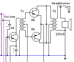
Our first example is one of an old type transistor radio where in the audio stages the output speaker was a typical 8 ohms. Such stages are impedance matched by audio transformers as depicted in figure 1 below.

Fig 1 - schematic of impedance matching of transistor audio stages
Typical values for these stages might be for our transformers, T1 5K to 2K CT (centre tapped) and for T2 250 ohm CT to VC (Voice coil) of say 8 ohms. The essential point here is that to perform satisfactorily each stage must be impedance matched to both source and load.
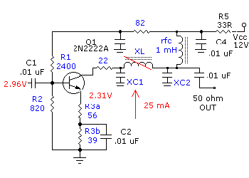
The next example might well be the input of a radio receiver connected to a 50 ohm antenna. Here we would use a tuned circuit amplifier. One illustration from that tutorial might be in the figure below.

Figure 2 - a schematic using a low pass filter for impedance matching
audio transformers
low pass filters
impedance
toroid cores
tuned circuit amplifiers