

Mobius winding techniques are a method of winding inductors, loop antennas specifically, to reduce the self capacitance inherent in the windings. Any inductor exhibits capacitance between windings, that's a fact of life. This capacitance in conjuction with the inductance forms a "self resonant frequency" for your loop or inductor. A loop antenna is simply another inductor by the way. For tuneable loops the inductance can be so high as to limit the useful frequency range and here mobius winding techniques can really help out.
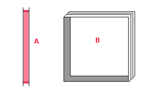
Unfortunately this is a little hard to explain, so let's use an example of a loop antenna constructed in a piece of aluminium channel. Our aluminium channel is fabricated into a rectangle as in figure 1a below. The loop is depicted in figure 1b, O.K. I don't win any drawing prizes.
The reason for the aluminium channel I'll explain much later, but it's important.

Figure 1. - loop antenna constructed in a piece of aluminium channel
For a square loop, imagine you had a piece of aluminium channel 20 mm X 20 mm (3/4" X 3/4") and 1200 mm (4') long. This is cut to have slots (blade width) through the sides only at about 300 mm (1') intervals so the channel can be bent back to form a perfect square.
Normally you would wind your wire around the loop so that each insulated winding is adjacent to one another, as sort of depicted in figure 1a and 1b.
A mobius winding technique, actually alternates the windings.
As I said, the mobius winding method, actually alternates the windings. It is said that except for start and finish where wires cross, all the "odd numbered wires" are adjacent to one another i.e. turns 1, 3, 5, 7..... Similarly, all the "even numbered wires" are adjacent to one another i.e. turns 2, 4, 6, 8..... That's the mobius winding technique.
Difficult to explain, impossible to depict with my drawing skills, I'll try.
Using the mobius winding method, you would wind turn 1 all around the loop hard up against say the left hand side of the channel. When you get back to start to do the next turn, you cross over so that turn 2 is hard up against the right hand side of the channel. Cross over again when doing turn 3 to the left side adjacent to turn 1 and so on until you have the desired number of turns.
The immediate benefit of the mobius winding method is the self-capacitance of the windings are reduced by about 50% leading to something like a four fold increase in the self resonant frequency. A further benefit is a broadening of the bandwidth of the loop. There is some reduction in the final inductance compared to a similar conventional loop of equivalent turns.
Good question! When I get around to loop antennas I'll cover it in more detail. For the moment, shielded loops (electrostatic shielding) respond favourably to the magnetic component of an incoming wave (signal) and eliminates the "antenna effect". This is also called electrostatic balance. The object of the exercise here is to improve the directivity of the loop which is usually the purpose of constructing a loop in the first place. They are however quite inefficient and probably -25 dB below a conventional antenna in performance.
The mobius winding technique improves the performance of a directional loop antenna, particularly at lower frquencies where conventional directional antennas would be impossible to construct physically.
The centre of a shielded loop antenna is always insulated to prevent it becoming a shorted turn.