

A regulated power supply is where by some means the output voltage is maintained or regulated within certain pre-defined limits.
To regulate small amounts of current the cheapest approach is to use a zener diode. Higher currents can be obtained from higher power zeners but I prefer to use dedicated I.C.'s in these cases. In one instance you can use a zener diode in conjunction with a pass transistor to extend the range of the zener regulator.

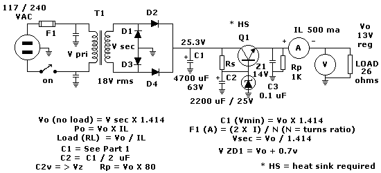
Figure 1 - schematic of regulated power supply
As with our previous design example we had a small unregulated bench supply of 500 ma for our projects. Now we have decided that it should become a well regulated, well filtered supply giving us 13V dc.
By using a series pass transistor we are extending the useful range of the zener diode as well as reducing Vo ripple. This is called "electronic filtering".
There is one large handicap with this circuit though. Under over-current conditions Q1 will most likely be destroyed long before F1 blows. Of course I have very cynical (practical?) friends who will tell you that if you buy up Q1 types at 5c each then in fact they are cheaper than most fuses anyway. Q1 usually requires a suitable heatsink.
Most calculations you will note are still in accordance with the example in basic un-regulated power supply I suggest you refer to that tutorial.
To calculate the value of Rs in the above figure you need to know the base current Ibfor Q1. This is the emitter current Ie divided by the transistor beta. It is preferable to meaure the transistor beta if you can (some meters have this facility) because the spread of beta on most transistors, even from the same batch, is about as wide as Sydney Harbour.
For the purposes of this exercise we will use the general purpose but cheap 2N3055 which will be mounted on a heat sink. Our beta measured 34 (if in doubt use mfrs. minimum beta from data sheet). Our base current is the emitter current divided by beta.
In this case we have 500ma/34 or 14.7ma. Also for decent regulation ZD1 needs a fair amount of current. I would suggest something about 25ma. Armed with this information, if Iz = 25ma minus the earlier Ib of 14.7ma = 10.3ma and if our dc voltage at C1 is 25.3V and our zener is 14V then Rs = [25.3V - 14V]/0.0103 = 1097 . I would use 1K.
The power rating of both the zener and Rs are calculated as follows:
ZENER Pd = [ ( Vin - Vz) / Rs] X Vz = [ ( 25.3 - 14) / 1000 ] X 14 = 0.16W
It is quite common to use a safety factor of 5 so I would opt for a 1W type zener.
Rs Pd = ( Vin max - Vz )2 / Rs = ( 25.3 - 14 )2 / 1000 = 0.128W (use a 1/2 watt resistor).
I have decided it is pointless including design for additional circuits for current limiting as this is provided even more economically with dedicated IC's. In fact all of the foregoing is mainly to give you the general basics. You would find in fact a dedicated IC regulator would probably be as cheap as this method.
basic un-regulated power supply
high current regulated power supply
variable power supply