
Philips describe their 602 mixer (SA602A) circuit as "a low-power VHF monolithic double-balanced mixer with input amplifier, on-board oscillator, and voltage regulator. It is intended for high performance, low power communication systems. The guaranteed parameters of the SA602A make this device particularly well suited for cellular radio applications. The mixer is a "Gilbert cell" multiplier configuration which typically provides 18dB of gain at 45MHz. The oscillator will operate to 200MHz. It can be configured as a crystal oscillator, a tuned tank oscillator, or a buffer for an external LO. For higher frequencies the LO input may be externally driven. The noise figure at 45MHz is typically less than 5dB. The gain, intercept performance, low-power and noise characteristics make the SA602A a superior choice for high-performance battery operated equipment. It is available in an 8-lead dual in-line plastic package and an 8-lead SO (surface-mount miniature package)".
Low current consumption: 2.4mA typical
Excellent noise figure: <4.7dB typical at 45MHz
High operating frequency
Excellent gain, intercept and sensitivity
Low external parts count; suitable for crystal/ceramic filters
SA602A meets cellular radio specifications
Cellular radio mixer/oscillator
Portable radio
VHF transceivers
RF data links
HF/VHF frequency conversion
Instrumentation frequency conversion
Broadband LANs
Here are the pin configurations of the 602 mixer in figure 1 below.
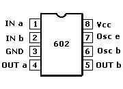
Figure 1 - 602 mixer pin configurations
IN a (Pin 1)
One half of the balanced input.
IN b (Pin 2)
The other half of the balanced input.
Ground (Pin 3)
Output high is about 1.7V less than supply. Output high is capable of Isource up to 200mA while output low is capable of Isink up to 200mA.
OUTPUT a (Pin 4)
One half of the balanced output.
OUTPUT b (Pin 5)
Other half of the balanced output.
Oscillator base (Pin 6)
This is the input to the base of the oscillator transistor. See data sheet for comprehensive explanation.
Oscillator emitter (Pin 7)
This is the input to the emitter of the oscillator transistor. See data sheet for comprehensive explanation.
V+ (Pin 8)
This connects to Vcc. Note comments about effective supply filtering and bypassing this pin below under "General considerations with using a 602 mixer".
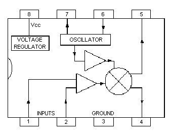
Figure 2 - block diagram of the 602 mixer
Vcc should lie between 4.5V DC min. and 8V DC max regulated.
Input signal frequency is typically up to about 500 Mhz, while typically the oscillator will work beyond 200 Mhz.
At 45 Mhz signal input the noise figure is quoted as 5.5 dB max although typically less than that.
The output impedance of the mixer (pins 4 and 5) is 1K5 (1,500 ohms) and the mixer needs to see that impedance.
The SA602A is designed for optimum low power performance.When used with the SA604 as a 45MHz cellular radio second IF and demodulator, the SA602A is capable of receiving -119dBm signals. The RF inputs (Pins 1 and 2) are biased internally. They are symmetrical. The equivalent AC input impedance is approximately 1.5k || 3pF through 50MHz. Pins 1 and 2 can be used interchangeably, but they should not be DC biased externally.
602 mixer data sheet - (109K) in PDF format.