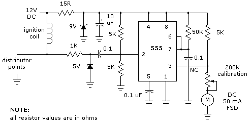
A tachometer is simply a means of counting the engine revolutions of an automobile engine. In this suggested idea a NE555 timer is configured as a monostable or one shot. The period of the 555 timer for our car tachometer is determined by the resistor from the 9V regulated supply to pin 7 (50K) and the capacitor from pin 6 and ground (0.1 uF). Time "T" = 1.1 RC or 1.1 X 50,000 X 0.1 X10 -6 = 0.0055 or 5.5 mS (milli-seconds).
The 555 timer receives trigger pulses from the distributor points. These are limited by the 1K resistor and the 5V zener diode, these are AC coupled to the trigger input through the 0.1 uF coupling capacitor. The 50 mA meter for the car tachometer receives calibrated current through the 200K calibration potentiometer (a linear type) when the NE555 timer output is high. After the timer has timed out, the car tachometer meter movement receives no further current for that part of the duty cycle.

Figure 1 - schematic of a car tachometer
Integration of the variable duty cycle by the meter movement produces a visible indication of the automobiles engine speed.
Supply is taken from the 12V automobile system and for the NE555 timer car tachometer is reduced to a regulated 9V by the 15 ohm resistor in conjunction with the 9V zener diode. Note that the 10 uF polarised capacitor must be placed physically as close as possible to the supply pin 8. It is depicted in the schematic diagram in this manner purely for clarity.
555 timer page
555 timer data sheet - (120K) in PDF format.